Adventures with the Lily58 #2: The Diodes Strike Back
In the first part of this series, I went through the process of selecting a split keyboard. I decided to go with the Lily58. Now that the PCBs had arrived, I began to assemble the keyboard with some trepidation. The following build guides were quite helpful:
- kata0518’s buildguide_en.md - the original build guide
- I found out too late that the keyhive build guide I was using was outdated and missing some pictures. The kata0518 guide contains all of the pictures, as well as updated descriptions.
- Japanese video build log - live build video with some suspiciously peppy music
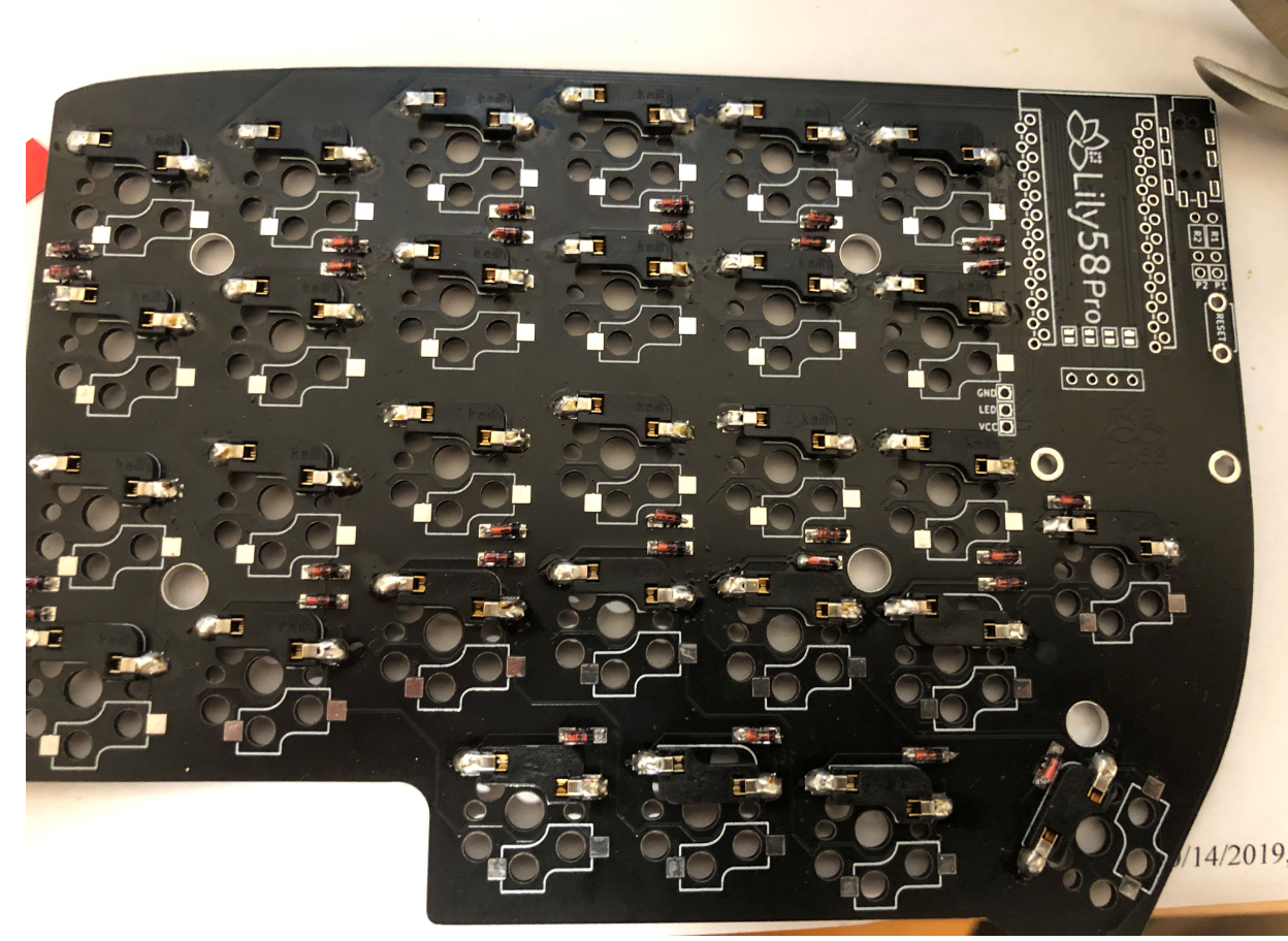
The first parts to populate were the diodes. Somewhat skeptical of my own soldering skills, I had ordered through-hole diodes. Despite my being a very middling electrical engineering student, the soldering turned out to be the easy part. Inserting the diodes was a nightmare. The PCB claimed to support both surface mount and through-hole diodes, but the holes for the through-hole parts were tiny. I quickly found that inserting through-hole diodes was several orders of magnitude harder than threading a proton torpedo down an exhaust port. Since no one was hovering over my shoulder and telling me to “use the Force”, I got out my trusty pair of pliers and dragged the diodes against their will through the gauntlet. This happened about 58 times.
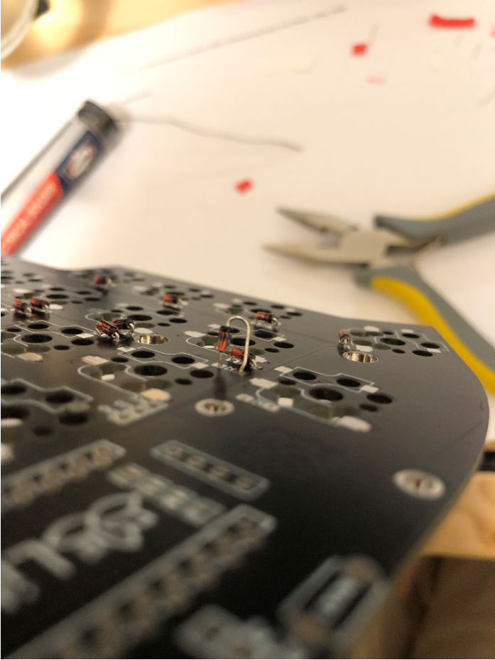
When the leads got bent, as they were wont to do, it was impossible to push them through the holes, so I had to clip off the bent segments and try again. Sometimes the diode leads snapped clean off, especially when I pulled straight from the other side. Pulling them at a 45 degree angle seemed to prevent this failure mode.
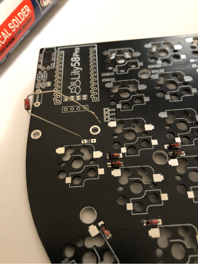
An emotionally overwrought collage of warped diodes. It would make a good book cover for Dante’s Inferno.
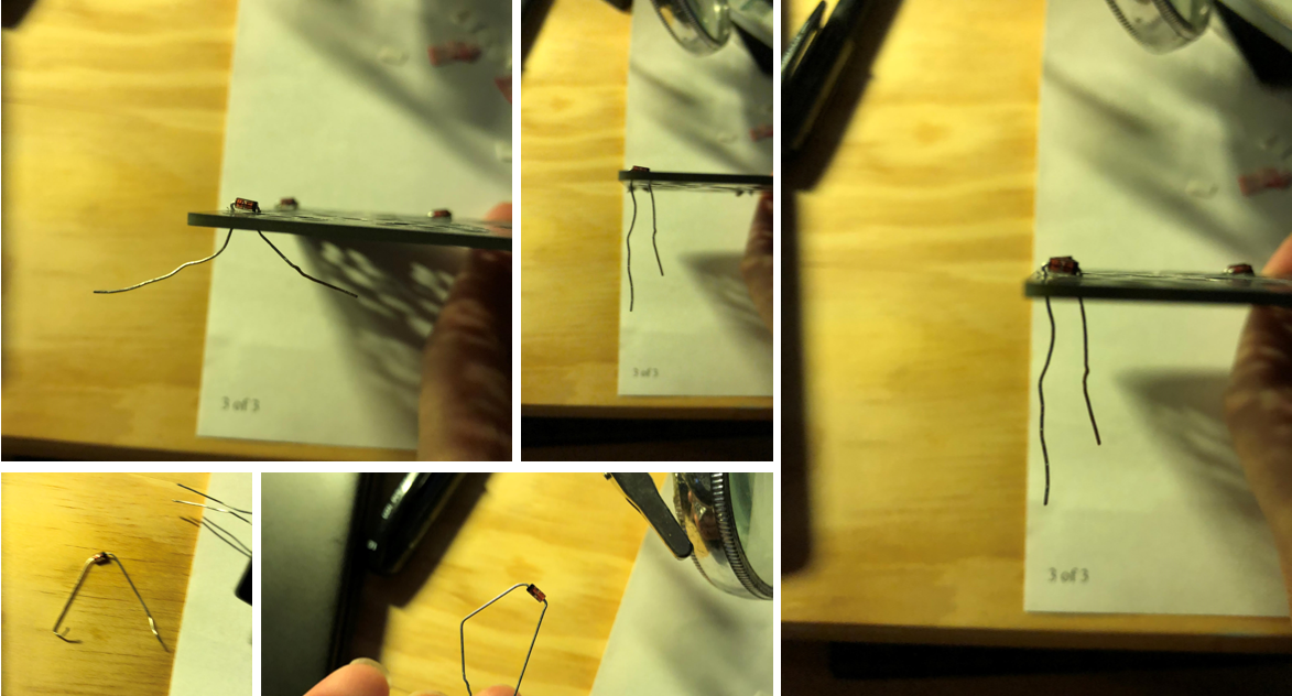
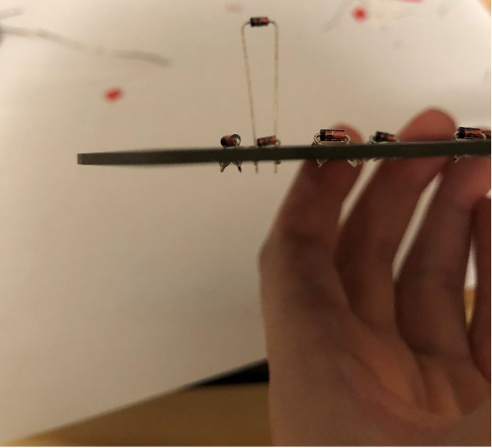
After a couple of tries, I learned the trick. Holding the board so that its plane formed a line to the eye, I mentally visualized pushing the lead “through” the board, as straight as possible. This strategy was somewhat helpful. Even so, it took a little over a week to install all of the diodes. After all of the soldering, I cleaned off the PCB with some 91% isopropyl from CVS.
The rest of the assembly was a cakewalk in comparison to the diodes. The hotswap sockets fit on and were soldered with no hitches whatsoever. Though the build guide recommended affixing them to the board with tape, I was fine without it.
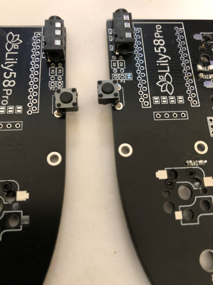
I used my multimeter in connectivity mode to remind myself which legs shorted together upon button press for these tactile push buttons. The actual soldering wasn’t too difficult, although I did have to carefully bend out the pins so they would fit into the comparatively wide holes. I didn’t have the original push buttons the board was designed for, but these worked, albeit with a little bit of flexibility in the leads. The TRRS jacks were a quick and simple soldering job.
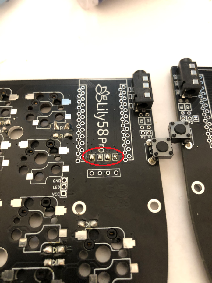
Per the build instructions, I shorted together the four connections under the micro controllers using liberal globs of solder.
Finally, it was time to install the micros! The first step was putting in the headers.
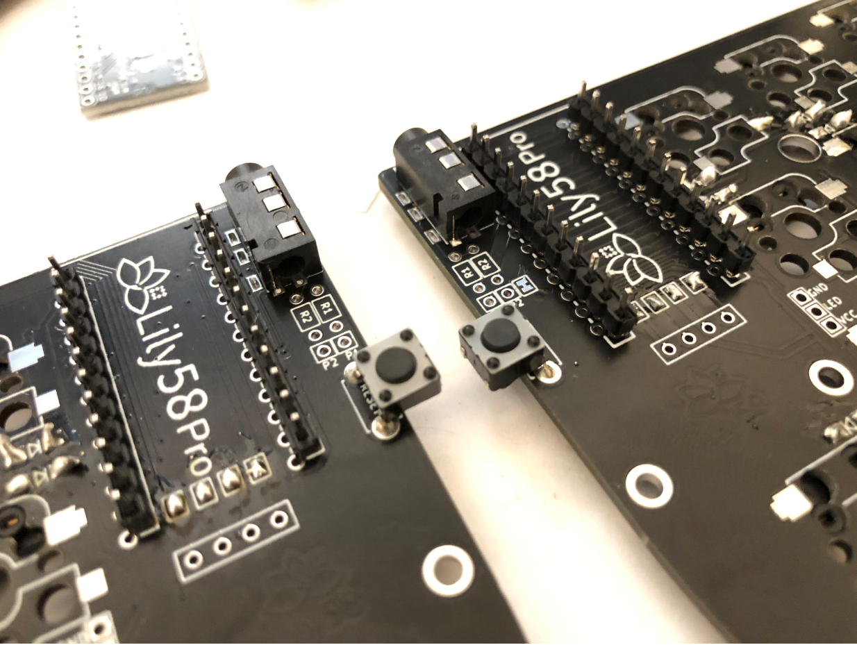
Since there were 4 lines of holes, it was a little tricky figuring out where to place the micros. After examining other builds, I determined that I should use the rightmost set of holes for both boards (when the top side of the board is facing up).
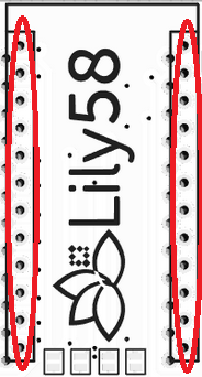
Upon running sudo make lily58:default:avrdude, the qmk firmware compiles (very slowly) and avrdude immediately tries to flash your attached microcontroller. It then flashes a message that instructs you to reset your Arduino Pro Micro.
Unfortunately, at this point I haven’t soldered it to anything and I need to short GND to RESET. What to do? I ended up going with the ghetto method below.
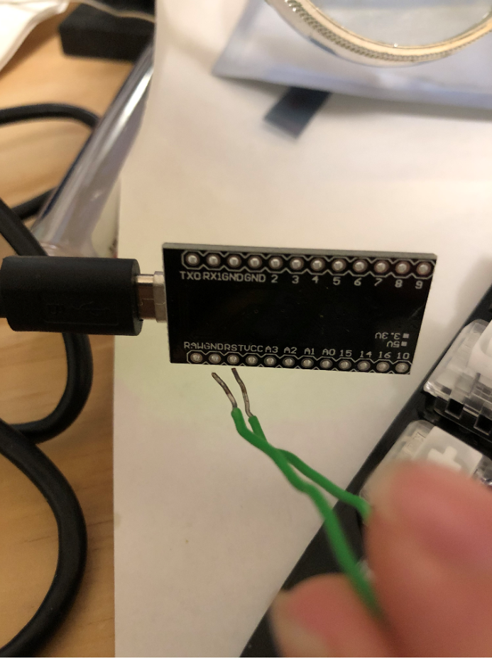
NOTE: Make sure you don’t have any virtual machines running on your computer when flashing. They can prevent avrdude from recognizing the Arduino. Not saying this happened to me.
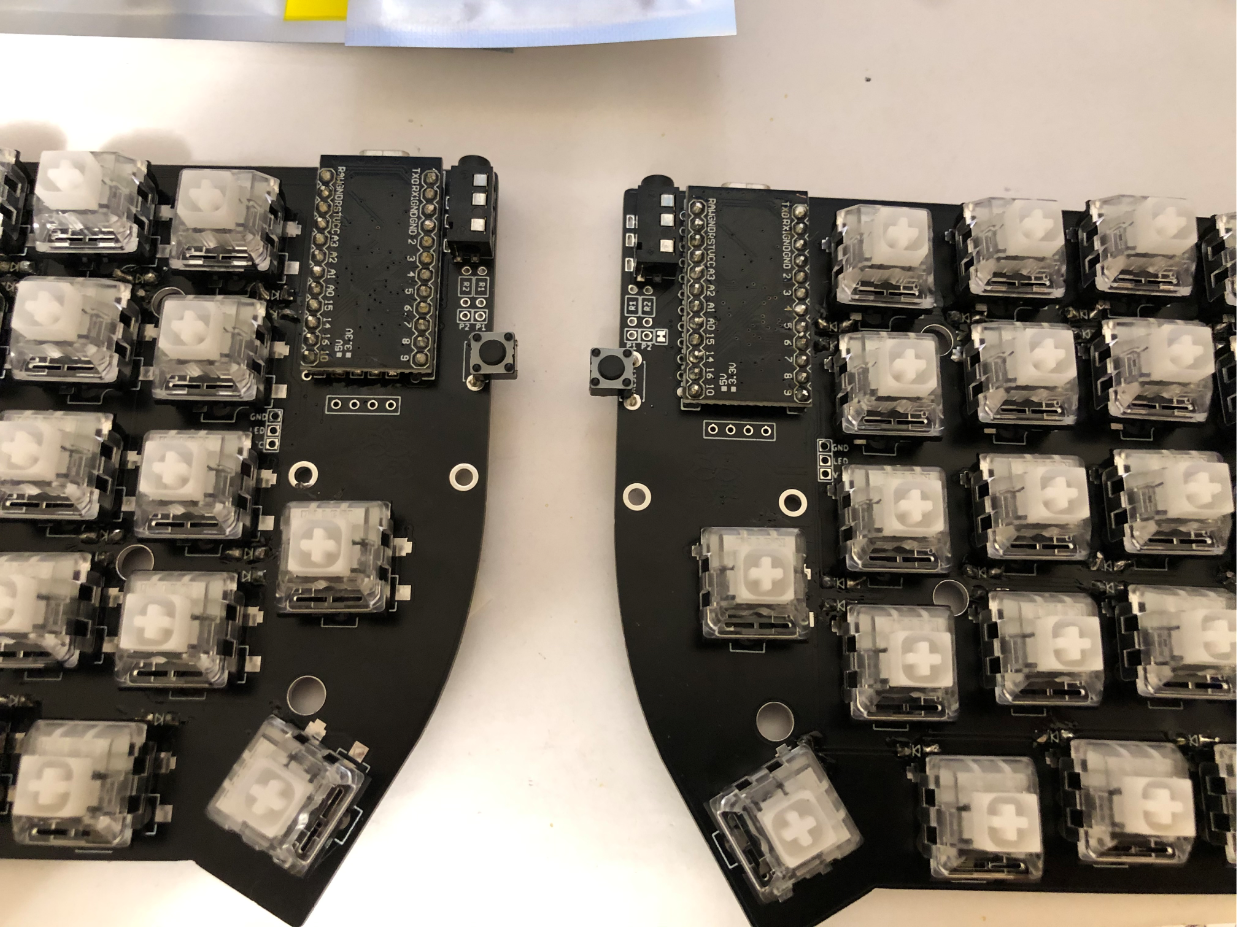
With the Arduino Pro Micros flashed, I took a deep breath and soldered them to the board. No going back now! I was little too eager to try things out, so I prematurely stuck in the keyswitches.
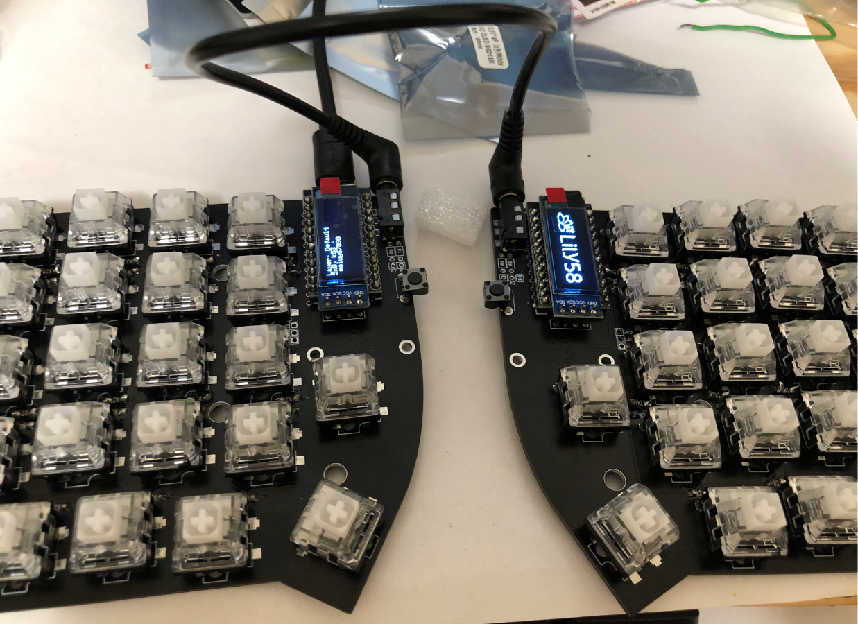
I put in the OLED modules for good measure.
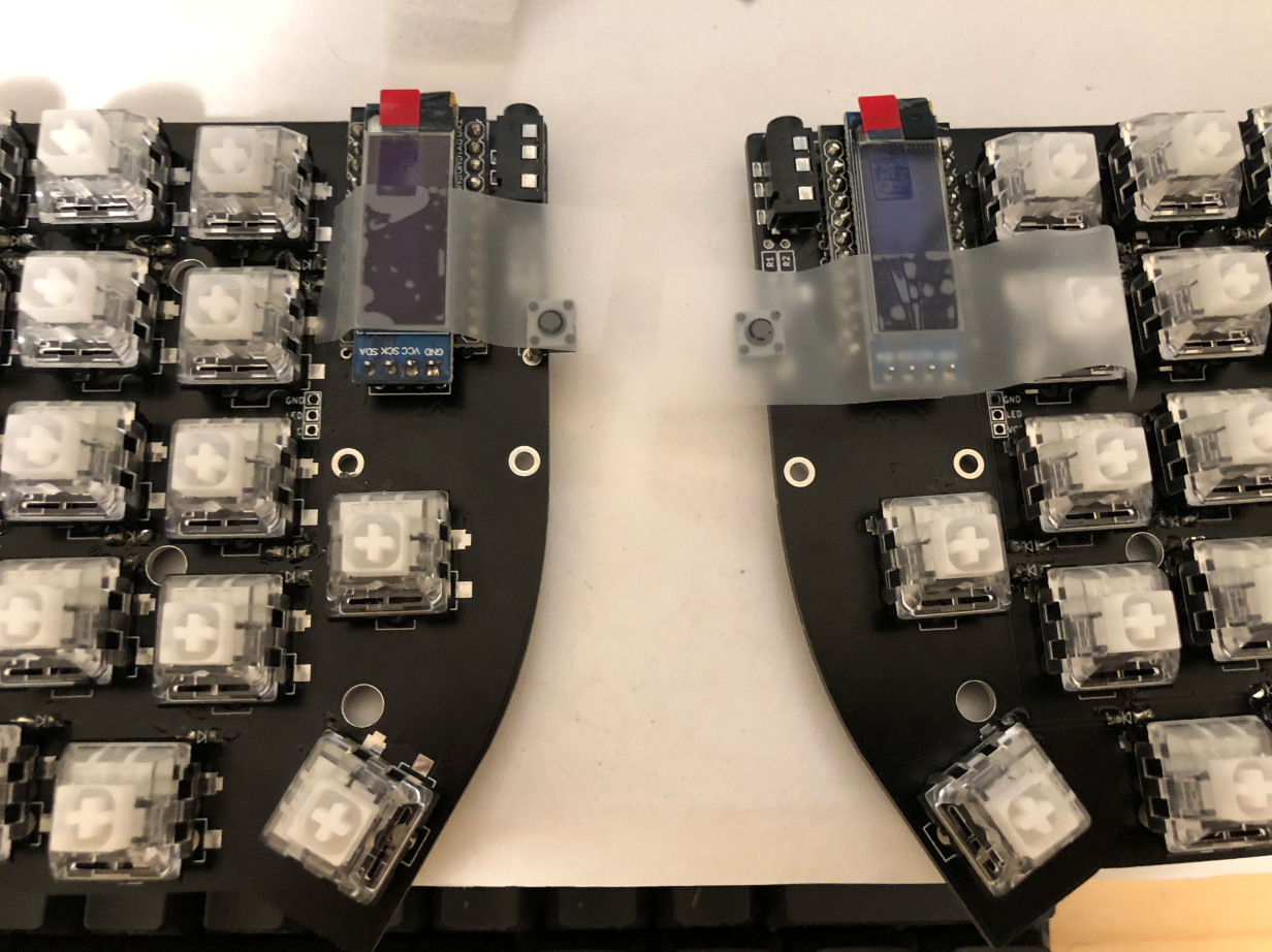
After hooking in the TRRS cables and then plugging in the USB cable, the OLEDs whir to life. It’s a good sign!
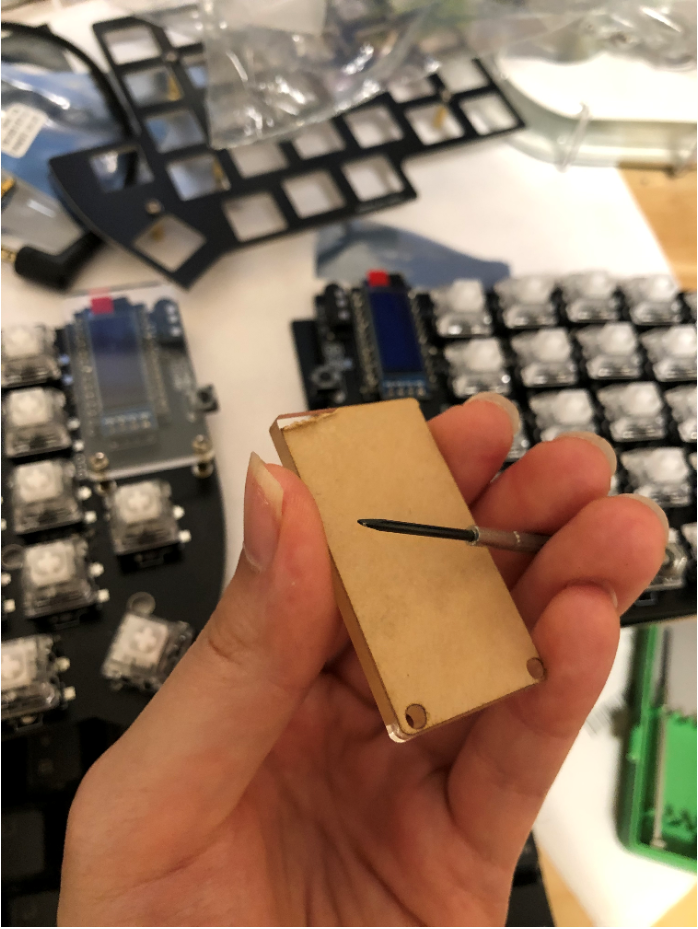
I used a mini-screwdriver to peel off the protective backing from the acrylic OLED screen covers and then screwed them in. One of the two screw holes on the cover is closer to the edge - that side should be closer to the rest of the keyboard. I didn’t understand what the build guide meant by “mount with the wider side outwards”, so of course I screwed it on the wrong way first. In hindsight, screwing on the screen covers should have been the very last thing I did. Later on, when I installed the keyswitches, I put too much stress on them and both of them cracked in different places. This why mothers should never let me come near their children or keyboards.
What’s a custom keyboard good for without RGB backlighting? Strangely enough, the build guide didn’t have any instructions on how to install the LED strips. I researched the issue on reddit and found the following, somewhat anticlimactic mapping for both halves of the keyboard:
- GND -> GND
- LED -> Din
- VCC -> +5V
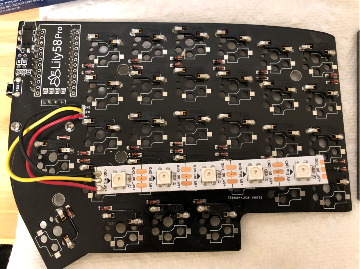
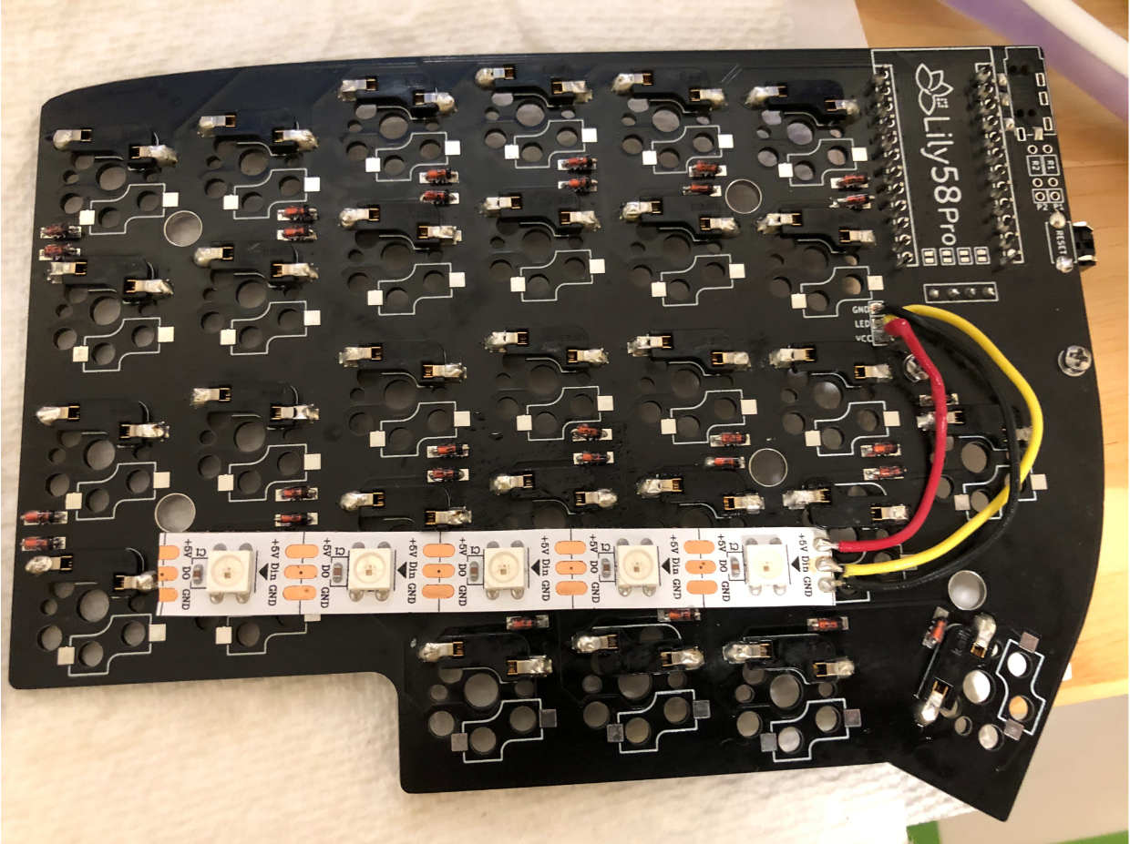
It worked admirably.
Next, I needed to install the keyswitches and top plate.
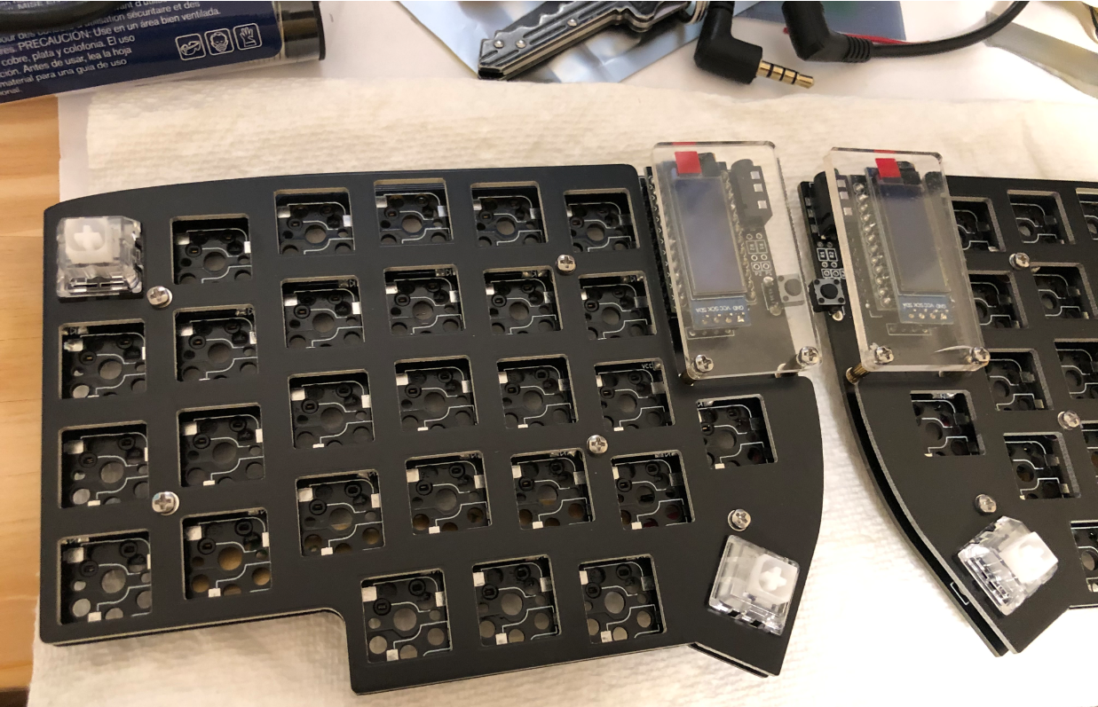
I pressed every key and looked for the appropriate reading on the OLED (the left OLED screen displays every keycode as it is pressed). But after installing all of the keyswitches, these three didn’t work!
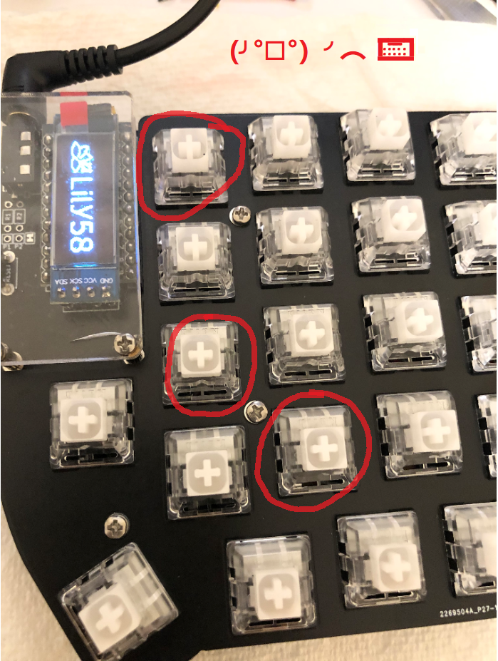
To be continued…